Bitx is an easily assembled ssb transceiver for all bands and for the Amateur Radio Operator-Hams, with very clean performance.Hams can home-brew the QRP TCVR by Using ordinary electronic components.
Thursday, May 8, 2014
Bitx 3B PCB second batch
The second batch of Bitx 3b PCB now has the following changes from the first batch of pcb's made.
1. Q16 is not on the main exciter PCB now, instead we have a additional PCB of audio mute
delay circuit. Please observe connections for integrating the connections from the schematics.
2. Two components have been added in the mic pre amp. 100UH and .001 at the mic pre amp circuit.
for better filteration of audio coming from the microphone.
3. Two pin connector's point has been added at
a. VFO for DDS optional use.
b. Audio to agc circuit
c. LM386 Audio Mute point taken to the Audio Mute PCB
Some Important Points:
1. We recommend the VFO coil to be wound with 2 nos of T37-6 stacked with about 40 turns plus or minus a few turns, for more stable VFO. The coil has to be glued with quick fix for better stability.
The second recommended VFO coil is on T50-2. Single coil. Both work as very stable VFO's
For Drift:
The VFO has two trimmers. The first towards the VFO coil is for fine tuning your VFO if your VFO coil is short of turns, so by adjusting the trimmer you can set the frequency of your VFO.
The second trimmer that is connected with the CONTROL circuit of FLL counter is the most important as te setting of this trimmer will determine the stability of your VFO. The trimmer has to be engaged in such a way as to observe no drift, if you see your vfo drifting tune the trimmer at such a point where you observe the VFO becoming stable, that is the correct setting point for the vfo's stability. The FLL has to be connected with RG174u cable for input to counter and the control point.
Subscribe to:
Posts (Atom)
Featured Post
My Journey with Amateur Radio: Sunil Lakhani (VU3SUA) Shares His Story Hello, fellow radio enthusiasts! This is Sunil Lakhani, also known...

-
.jpg) After the Bitx3C ADE-1 we present the Bitx3C SBL-1 . The schematic is being published here. The Bitx3C SBL kit will be soon available ...
After the Bitx3C ADE-1 we present the Bitx3C SBL-1 . The schematic is being published here. The Bitx3C SBL kit will be soon available ... -
 For those of you wishing to build the Bitx 3 with ADE-1 Mixers the good news is that the PCB's are ready for the Bitx Version 3C. Ther...
 -
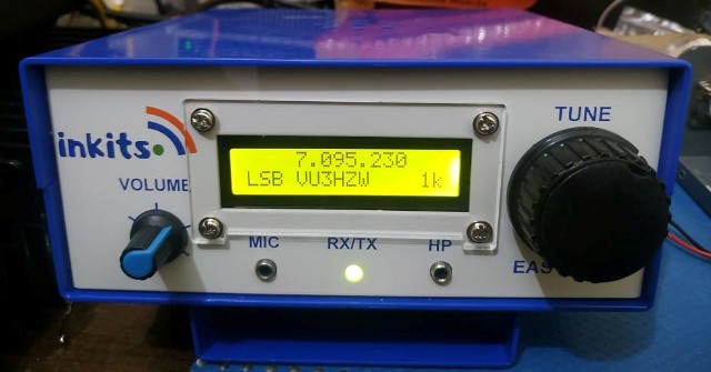
 NEW VERSION OF BITX KIT AVAILABLE After a break of few years we are back with our new Easy Bitx Kits. The Easy ...